LED floodlight 50W repair
Intro
A little over one and a half year ago we ordered a bunch of LED floodlights to improve the illumination situation in our basement workshop rooms for the Repair Cafe events. Prior to those floodlights there were about 12 spotlights each with a 200W bulb. Despite the number and wattage the lighting situation was suboptimal and at each event we had to add four 500W halogen floodlights to reach acceptable work conditions. Totalling at more than 4kW this was quite straining on our power lines, heat up the rooms quite a bit and caused frequent overloads and power outages, especially if other devices with a high power consumption were in repair attempts. So we decided to replace half of the spotlights by 50W LED floodlights to cut down on power consumption and increase the overal illumination. Over a few weeks we evaluated a few floodlights (because not only wattage was important but also that the light color fitted into the existing light situation) and settled on a set of good warm white 50W LED floodlights. The illumination was much better than we imagined and in full setup used only 1.5kW of power. Less than half of the usage for what we can only describe as a near-daylight situation in our rooms. Very nice :-)
Problem
Near the end of 2016 one of the floodlights began acting up and had to be taken out of service. When turned on it was fine for a second or two but after that it began flickering like mad.
Of course this was unacceptable and while we had to replace it with another floodlight for the time being the concept of the Repair Cafe is to repair broken stuff. And that's whar I decided to do with this one. From the behavior I initially guessed that probably the power supply had broken but as I later found out that was a red herring.
Analysis
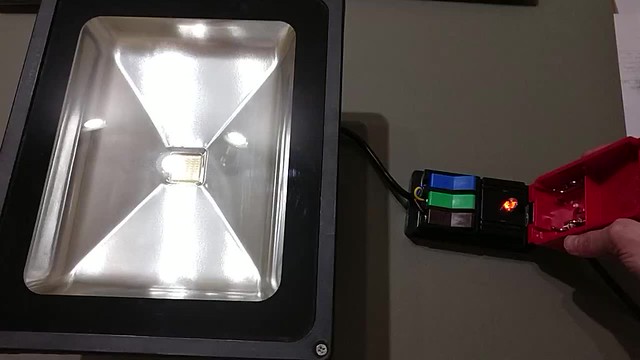
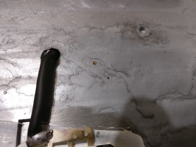
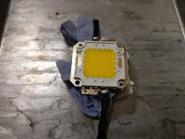
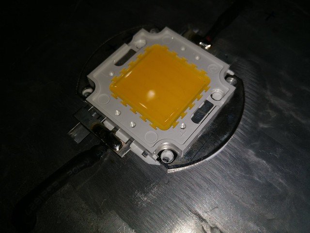
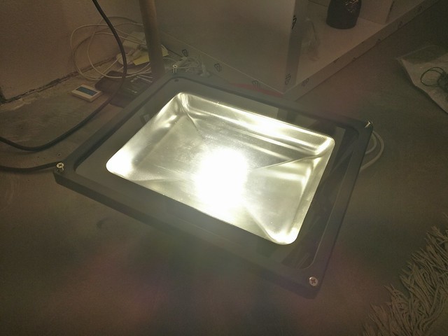
At first I opened the back with the power supply but that did not result in progress as the incoming cable and outgoing ones to the LED element were all isolated and had (without damaging it) no possibility for putting on multimeter measurements. So it had to happen on the LED element itself. Opening the front of the floodlight was also not really an issue. Just four screws at the frame and four screws on the reflector and the LED element with its connectors was accessible.
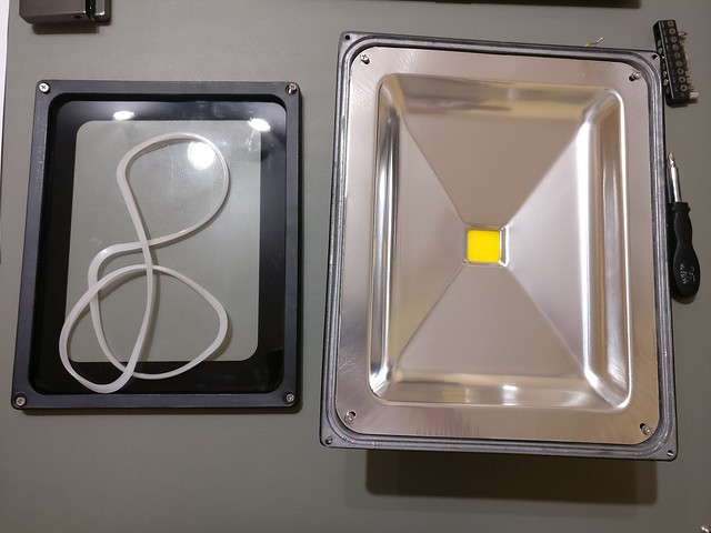
On a first glance not too bad and rather clean but upon closer inspection:
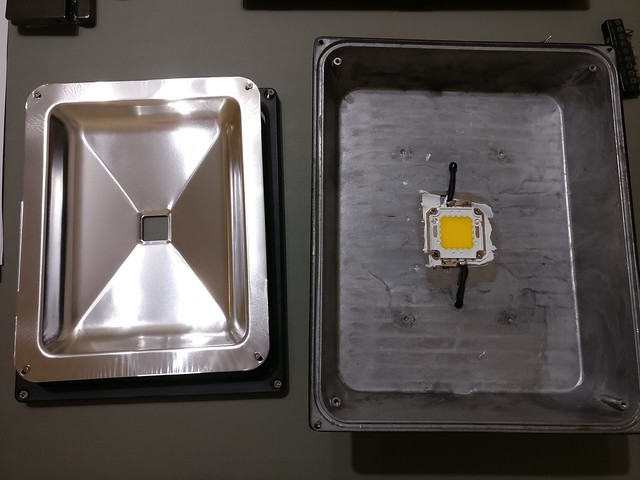
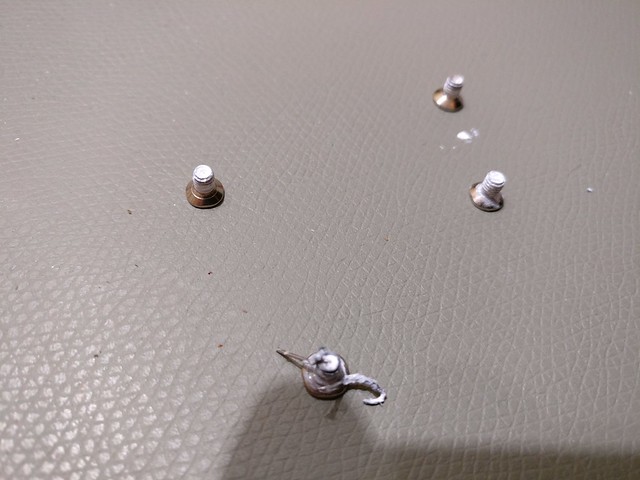
Oh wow, one of the LED elements screws seems to have been messed up during installation and they fixed it by using a piece of wire and some force. Well, it seemed stable so I did not care about it too much. But then I recognized those little gems:
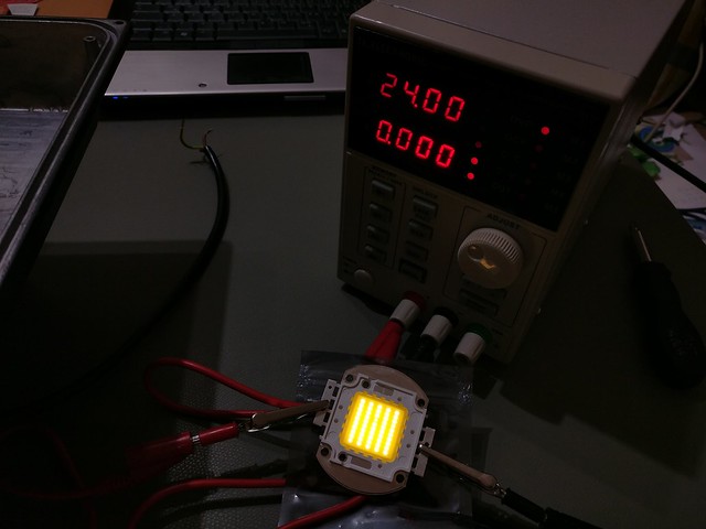
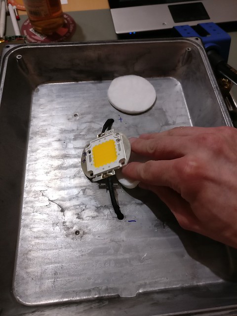
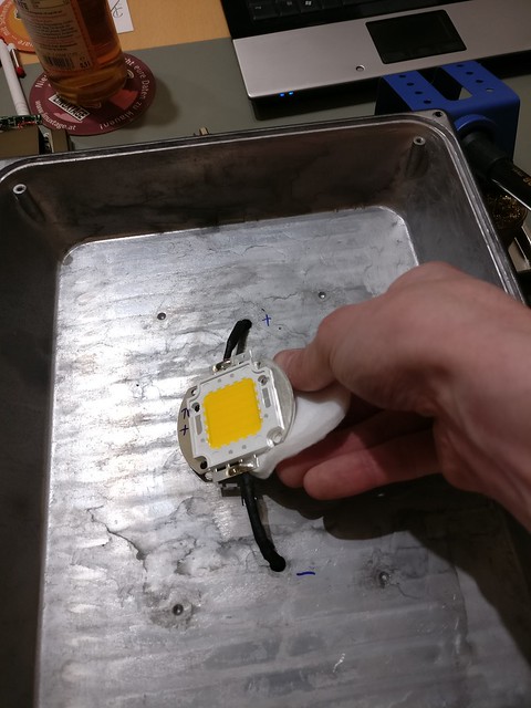
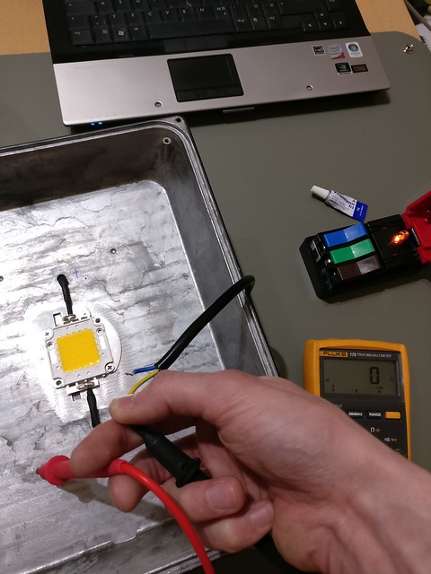
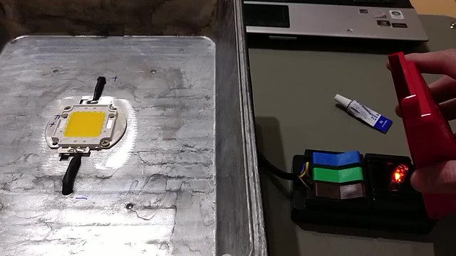
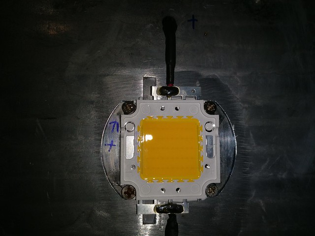
Nice, some solder balls rolling around in the case. Veeeery bad. I cleaned everything out, checked that no shorts were present and re-tested the light. No improvement but I recognized something different. I pulled out my power supply and tested the LED element directly:
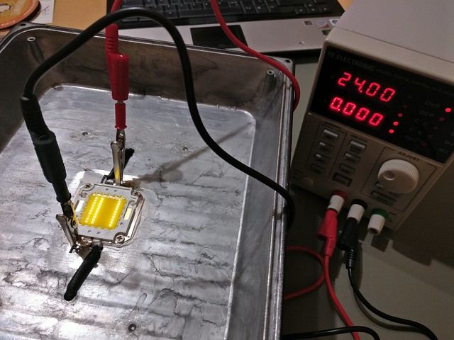
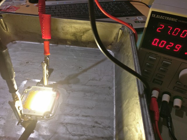
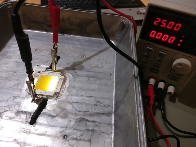
Oh wow, it seemed like the LED element itself was the culprit. It was not visible when the light was plugged in because of the sheer amount of light but when brought up just with minimal supply voltage by an external power supply it became apparent that half of the LED stripes in the element had failed and when brought up to higher voltage also all but one ceased to work. I now assumed that the power supply in the floodlight had some sort of failsafe mode and turned off temporarilly when the LED element drew an abnormal amount of power, causing the flickering.
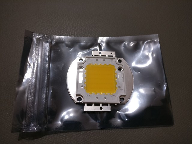
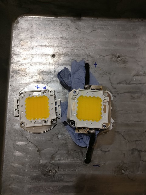
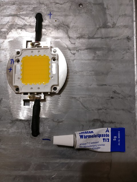
I changed my approach and ordered a 7$ 50W warm white LED element from eBay. All of those have identical dimensions and comparable power supply specs so it was relatively easy to find one. I went for an element with a bit larger metal base. I chose that one to improve the heat distibution to the floodlight case and let the LED element itself work with a bit lower temperatures.
In my experience most LED elements nowaday fail because of problems with heat distribution.
Repair
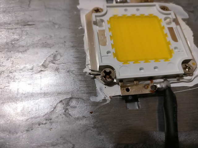
After a week or two the replacement LED element arrived and I could finally start with the repair attempt. After unscrewing the old LED the lapse with one screw during assembly was visible in its whole beauty.
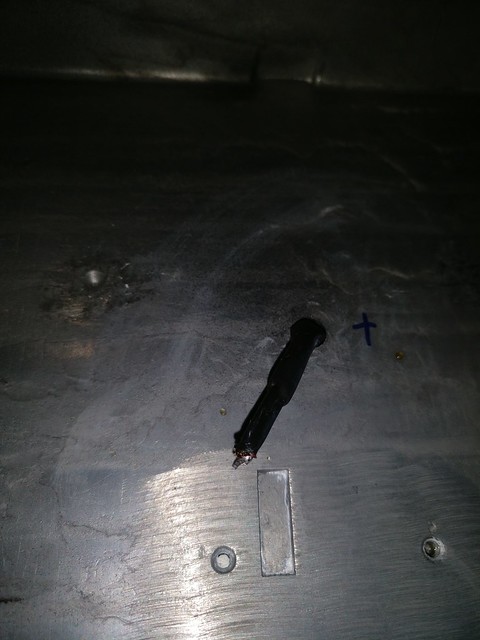
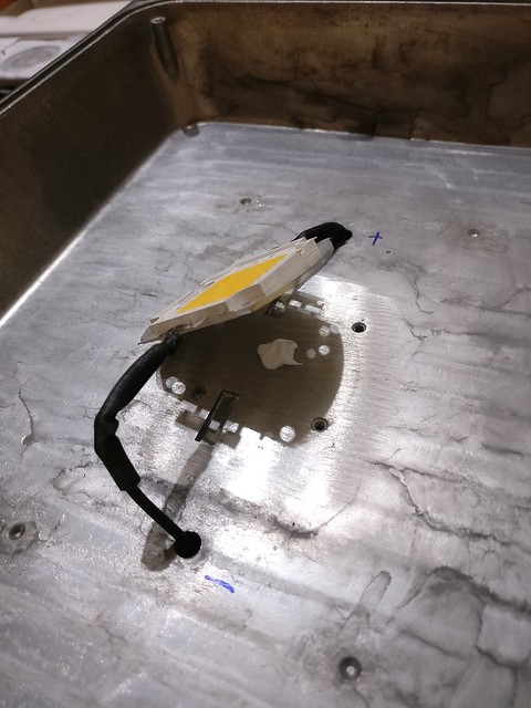
I then began preparing the element for desoldering. Lifting it from the case was important to reduce the heat loss, therefore I lifted the element with some paper.
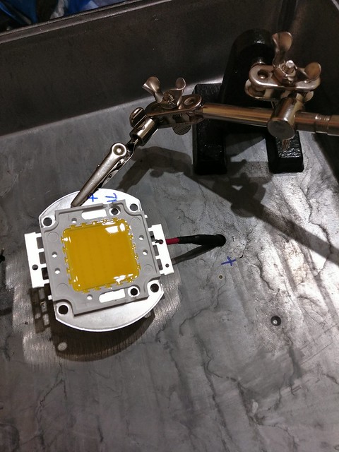
And just before desoldering I remembered to check the new element once more and mark the polarity so that I do not accidentially solder it backwards.
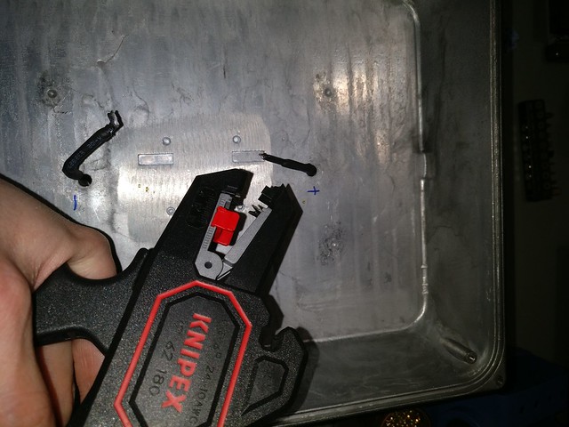
Finally everything ready I fired up the solder station with the largest tip I had around. This took a bit and called for a short break.
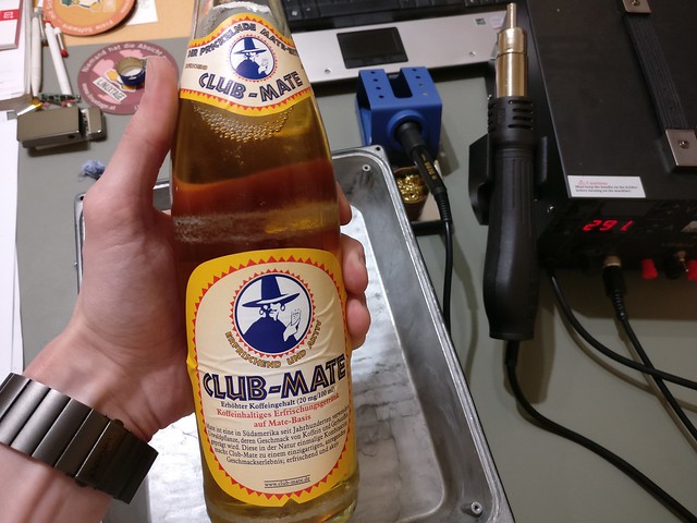
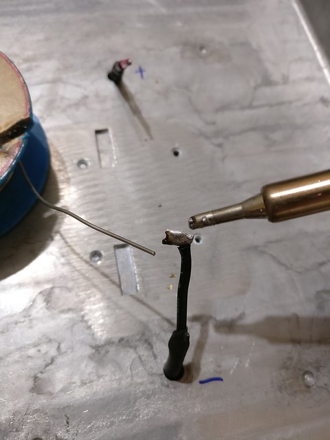
After the Mate the desoldering began and unexpectedly required higher solder temperatures than I expected. The solder was a bit reluctant to come off and I had to turn up to 350°C to get the wires off.

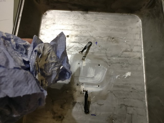
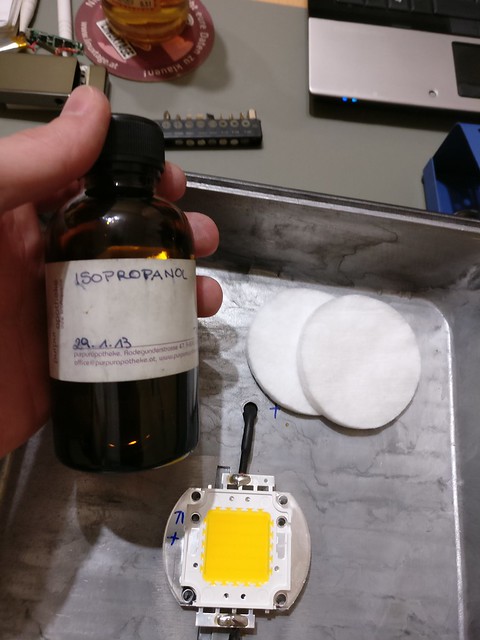
Following the removal also the old thermal compound had to be removed. Quite a mess but finally with lots of paper towels and Isopropanol I got it relatively clean.
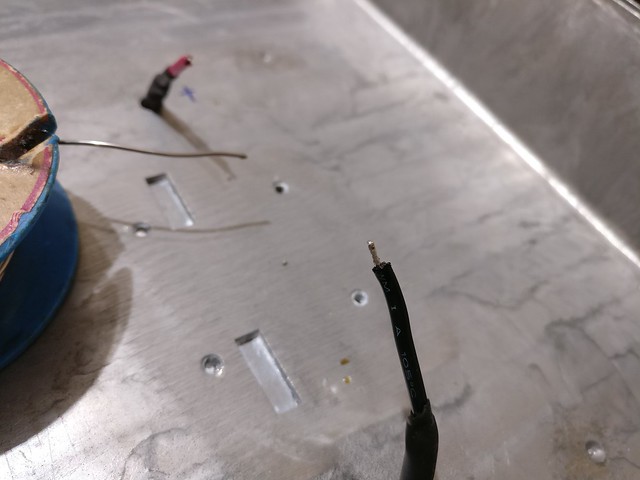
Next up was preparing the wires for the new element. That meant removing all of the prior solder, extending the contacts a bit and tinning the wire tips.
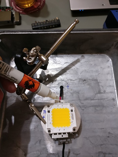
Followed by the soldering of the replacement LED element. Don't forget to use plenty of flux for proper contacts.
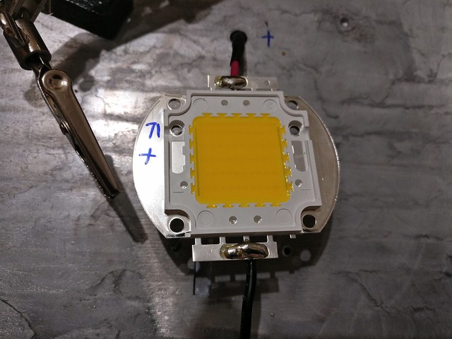
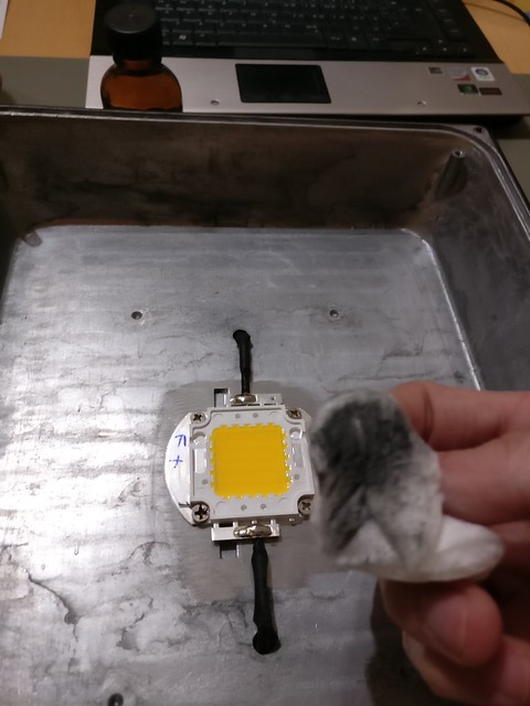
Cleaning the element once more and finishing properly was done. This also included the backside of the LED element, I didn't rely on a clean surface there either.
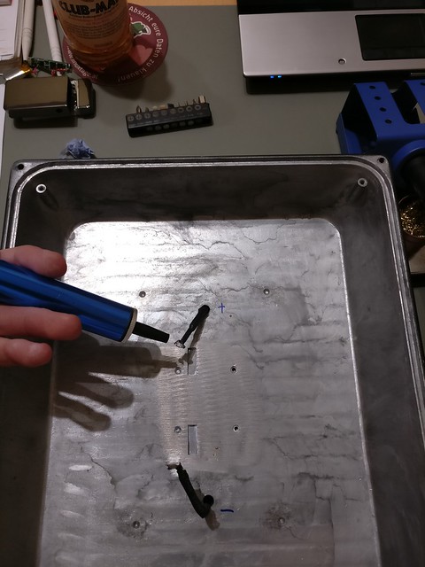
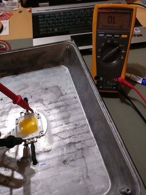
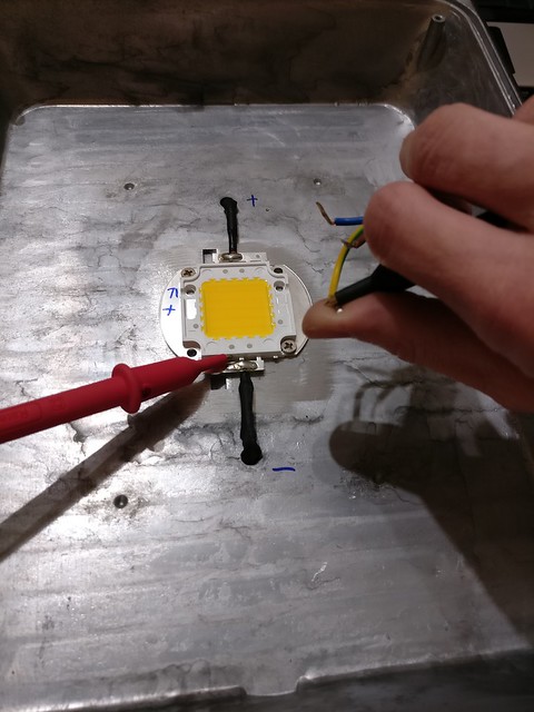
Preparing for the first test after replacement required some additional checks. I visually checked if there were no solder balls around and checked with a multimeter if all connections were ok, earthing was correct and no shorts present.
The first test was done quickly, only leaving the element turned on for a few seconds. There was no thermal compound yet and the LED was not tightly screwed on the case. I expected the heat to build up quite quickly that way and so I had to hurry too. The test was successful. Just during the cooldown of the element I recognized a single LED inside the LED block to be darker than the rest (visible for a short time in the middle of the LED element) and checked visually if it was working and no aparent damage present. Everything looked fine there so I continued.
(ignore the background sound, I was watching some Youtube during the solder job and forgot to turn it off...)
Properly adding thermal compound and making sure that there were no air traps inside took a bit of patience. For that I put a large drop into the middle of the case and lowered the new LED element with circling motion. When it was down I pressed with a bit of force until the thermal compound was spread visibly on all edges of the LED element.
Screwed everything tightly, also re-adding the fix for the messed up screw. And another round of cleaning again. I should have probably waited for this step for thorough cleanings, could have saved me a few minutes in the prior steps. I didn't expect the prior steps to create that much mess again.
After that I did a visual check one last time if everything was tight and rigid, screwed in the reflector and screwed on the glass frame. Looked exaclty like before the repair procedure.
Result
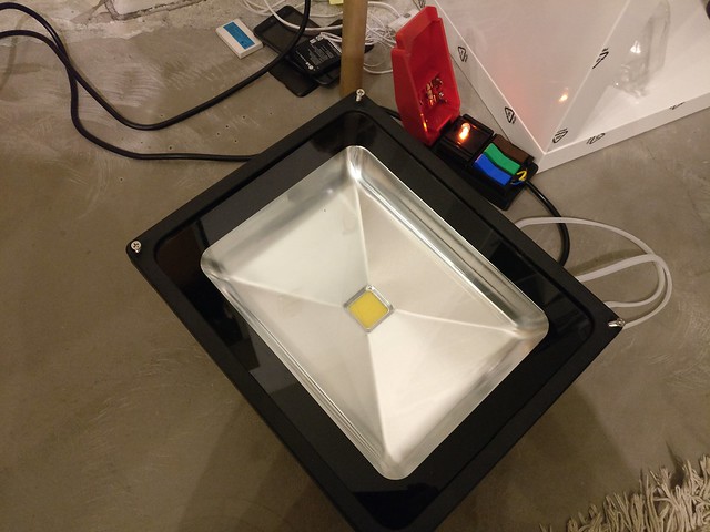
The (almost) final test was satisfying. The flickering/pulsation was gone and everything looked fine, just of course a bit brighter than with the old element. The following final test was to let it sit there turned on for two hours and check the temperature. The case didn't heat up too much, the light intensity didn't change and all individual LEDs in the LED element were still functional.
Conclusion
In the end the whole procedure did not only require a replacement LED element worth only a few € but I also had used more of my repair equipment than I expected. Of course the repair would have been possible with less equipment too but some steps would have required a bit more accuracy and patience. The repair attempt itself was successful and the floodlight is now working as expected. Probably even better than originally as I removed some loose solder balls and undertook measurements that the heat from the LED was dissipated as good as possible.
Used tools:
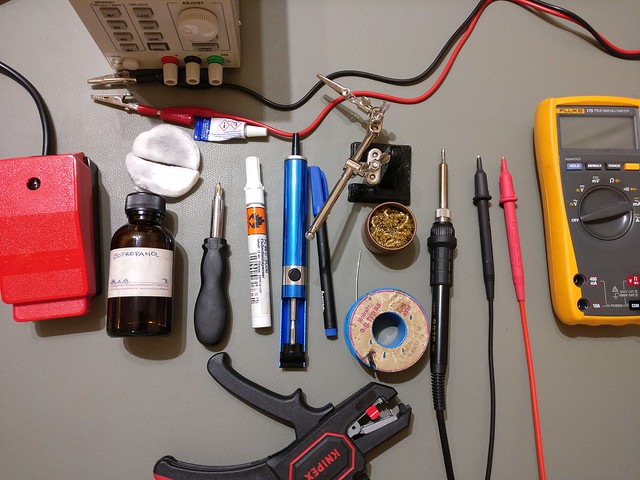
- power supply
- banana plug wires and crocodile clips
- solder station
- solder (leaded)
- solder sucker
- multimeter
- solder tip cleaner
- solder flux
- wire stripping tool
- screwdriver with bit
- isopropanol
- cotton swabs
- marker
- thermal compound
- third hand tool
- Cliff Quick Test tool (for safe checking of bare wires with 220V supply)