Author: admin

  • LED Cube: Smooth BAM-style brightness modulation

    I already explained that I use Bit Angle Modulation (BAM) in contrast to Pulse Width Modulation (PWM) in the logic which controls the brightness of individual LEDs in my LED Cube. During the implementation of the brightness routines in my source I realized that it worked pretty as expected at high refresh frequencies but I got very weird results for lower refresh rates.

    Especially if I set the brightness to 50% (decimal 128) the LED had a clearly visible on/off-pattern of 4Hz in when running the cube at 1kHz. The explaination of this is pretty straigtforward: when the brightness is 128, standard BAM causes the LED to be active 50% of a full 256-cycle. 1kHz has ~4 full cycles and therefore the LED turns on and off ~4 times/sec.

    Wouldn’t it make more sense to have the LED alternate on each refresh, so that the average brightness is still 50% but the LED turns on and off with a period of two refreshes instead of 256? Similar to PWM but without the requirement for very high modulation rates?

    My overall solution to tackle this issue was to add a simple counter which is increased with each refresh. When it reaches its maximum at 256 it’s reset to 0 again. I use this counter to look up a bit-value in a table, which results in the bit to check for in the brightness value in each cycle. I then use this bit to AND it to every single brightness value of each LED and if it’s non-zero the LED is turned on for this refresh. The initial values for this lookup table indicate the bit-values and resulting on-time for each bit of the brightness value. See the original code here. Of course this version still suffers from the problem described above, if the value is 50% the LED is on for the last 128 cycles of the 256-cycle period which leads to a slow and visible on/off blinking effect at low refresh rates.

    The remedy for this is simple though, as the check-values are already in a lookup table. Just distribute the check-values much more evenly in the table and split up the connected on-time for each BAM-bit across the 256-cycle period. The resulting table is this. In this table every bit-value is strictly evenly distributed and spaced relative to each other so that the same values always have the same period.

    The result of this change, which involved the usage of some LibreOffice Calc trickery, now allows for much smoother brightness control at much lower frequencies. Though there are limits to this. If the brightness is 1, it will still cause a visible 4Hz blinking at 1kHz refresh rate of the cube. There’s no way around this besides limiting the minimum refresh rate to higher values. But in contrast to expensive PWM and unmodified BAM modulation, this variant should reach a relatively regular ~32Hz flickering already at a brightness as low as 8 (~3%).

    So in pseudocode the looping and brightness algorithm for the LEDs works as following:

    int counter = 0;
    int bamBit = 0;
    
    while (true) {
      // calculate if each LED is on or off during this refresh
      bamBit = getBamBit(counter); // get current BAM bit from lookup table
      for(int layer=0; layer<COUNT_LAYERS; ++layer)
        for(int x=0; x<COUNT_X; ++x)
          for(int y=0; y=COUNT_Y; ++y)
            ledsActive[x][y][layer]  = ledBrightness[x][y][layer] & bamBit;
    
      // display this refresh
      displayCube(ledsActive);
    
      // reset counter at end of whole modulation period
      if(counter > 255)
        counter = 0;
    }

    Update: I’m not sure if this really works in practice as it should in theory. Until today I’ve used a not perfectly even distributed version of the lookup table (see this version) which I smacked together by just mixing up the values in a much simpler way (splitting the blocks and putting them together in a more distributed fashion) which was much quicker to come up with. Nevertheless I have the impression that the flickering has not smoothened at lower refresh rates and brightnesses as expected. I’ll have to look into that sometime in the future again and make a better comparison of both versions. But yet it’s still much better than the unmodified BAM brightness algorithm.
  • LED Cube: Status 2013-02-10

    Just a quick status update on the progress of the cube since my last post.

    On the hardware side there has been activity on two different topics. At first I had the opportunity to analyze my circuit and try to find out what’s causing the ghosting effect at higher framerates using a friends oscilloscope. This involved getting comfortable with the usage and application of an oscilloscope in general and then trying to find out the different effects of different measurements and several different wiring variants of the transistors on the board.

    From LED Cube Images
    From LED Cube Images

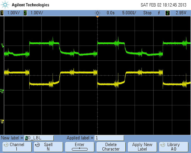
    This took a good part of a Saturdays afternoon and in the end I was pretty confident that the cause of my problem is that the base of the PNP transistor is not recovering fast enough to the blocking voltage as the IC leaves the pin floating after disconnecting it from GND. Attempts to remedy this with pull-up resistors allowed me to increase the refresh rate of the cube about 10x up to ~1kHz without noticeable ghosting but that’s not really sufficient for my taste. My target is to allow up to 50kHz refresh rate on the 3x3x3 cube without noticeable afterglow of the LEDs. On the internet I found several topics where similar problems are discussed and all of them seem to have a common solution: add a Schottky diode to bring up the base voltage level faster. I had no schottky readily available so I unsoldered one from an old PC motherboard and used it to cover one of the three LED layers on the breadboard. Results are promising so far, I hope this still works when all three layers are equiped with a schottky. For now I think I can manage to work with lower cube refresh-rates until I’m able to pick up correctly dimensioned schottkys for all three layers. Until then this will be the situation on a single transistor at 5kHz (Yellow: base current; Green: collector current):

    From LED Cube Images

    Update: Short explaination to this graph. It was measured by hooking the oscilloscope to the base and collector of one layer PNP transistor. Pull-Ups are in place. Clearly visible (by the "knobs") are the layer switches causing some disturbance each time. When the layer gets activated the transistor instantly switches to conducting mode. But when it is disconnected again, it requires about half of the next layers visible time (~2us) to completely go into non-conducting state again. The faster the refresh-rate the longer the afterglow in each layer…

    The last few days I’ve also been tingerking and thinking of how I could build the cube skelleton. I found no practical way to solder the LEDs together in a stable manner without adding additional wire. So yesterday I purchased a bit of iron wire and tried to solder the first layer. I drilled a few holes in a wooden plate, put the LEDs in it and soldered the LED pins together where possible.

    From LED Cube Images

    Next I prepared the iron wire, straightened it, cut out the parts…

    From LED Cube Images

    … prepared them for being soldered together with the LEDs to build the first layer…

    From Building LED Cube

    … and failed miserably, because the solder did not stick to the iron wire

    From Building LED Cube

    And I have absolutely no idea currently, what went wrong. Obviously another gap in soldering knowledge which I have to close when I want my next attempt for creating the LED grid to be successful.

    At least on the software side there has been much more progress and success. I created a Github project for the LED cube driver software and improved and refactored the whole code several times now. So far I’m pretty confident that I created a quite flexible architecture and codebase so that it should be scalable for the 8x8x8 cube with minimal effort. Furthermore the animation framework is pretty stable and capable enough that I was able to create a new animation from scratch (one where you can move the bright LED using the cursor keys) within ten minutes. Each animation is encapsulated in a single class and completely independent from the cubes real refresh-rate. Notable features of my code which are finished (for now):

    • smooth BAM (Bit Angle Modulation) for controlling the brightness of single LEDs
    • console status output and …
    • … keyboard control for the animations, I/O via ncurses library
    • flexible animation architecture, independent from cube refresh rate
    • stable timing framework for controlling animation and cube refresh rates
    • a small set of prototype animations (whole cube pulsating, a single linear moving light, single random LEDs pulsating, a keyboard-controllable light)
  • Homemade fluid solder flux

    When I tried to solder IC components for the first time one of the mistakes I made was that I did not use solder flux during soldering. The results (inevitable failure) can be read in the correstponding blog post.

    Nevertheless when I tried to find out which solder flux to buy I realized that this was a pretty expensive attempt as commercial solder fluxes sell in almost unrecognizable tiny quantities at extremely high prices. Think of something like 10EUR for just 10ml and then this stuff is often extremely poisonous and should only be handled with good ventilation. The one I had a look at initially had three pages of health-instructions in its data-sheet. Inspiring confidence.

    Well, I decided to don’t go that route and pick up good old colophony (‘rosin’) which was the primary flux component for decades. What has been good in electronics 20 years ago should be more than sufficient for my purposes. And it’s pretty cheap, I could pick up 20g for just 2EUR. I tried soldering SMD again using colophony and of course that time was a success (granted, also using a clean solder tip that time). But it was a bit cumbersome as colophony is in cristaline form and I had to scratch a bit of it for usage which also involved tiny bits and pieces flying off in all directions.

    So I decided to take a hint from somewhere (don’t remember where), solve it into some isopropyl alcohol and fill it into a small flask with a pipette I still had at home from some overdue nosedrops. This should make a decent selfmade liquid solder flux for hobby purposes. Picking up IPA was no problem, I got 100ml for 3.85EUR at the local drugstore.

    From Homemade liquid solder-flux
    From Homemade liquid solder-flux

    Then I scratched up a larger portion of the colophony so that it was in tiny chips and dust…

    From Homemade liquid solder-flux

    …and poured it into the flask which was half-filled with the IPA. The larger parts of the colophony took some time to dissolve (barely visible in the photo). I added colophony until the solution had a viscosity which was good to use on PCB.

    From Homemade liquid solder-flux

    Using a drop of this solution on the IC pins before soldering worked like a charm and I was able to solder the IC onto the PCB without much hassle (can be seen in my first test posting).

    One note though, the usage of colophony leaves back some light brownish residues after solding. Those are completely inert, do not interfere with the circuit and cause no harm. To the contrary it has even a certain conservation effet. If desired those residues can be removed also with isopropyl alcohol (still got plenty of it left from the purchase, remember?) but I decided to leave it on for the nostalgic effect 😉

    Some warning notes: Although colophony is far from being as poisonous as other fluxes, the fumes should not be inhaled and skin contact should be avoided as it can cause allergies. Make sure the soldering place is properly ventilated and do not touch the fluids. If it comes onto your skin, wash it off with lots of water and soap.

  • LED Cube: Finished 3x3x3 prototype circuit, first hardware issue

    In the last few days I’ve spent some time in the evenings/nights to set up a complete prototype circuit of the 3x3x3 cube on breadboard and create the first parts of the driver software.

    There have been some minor issues (e.g. realizing that the larger breadboard has a different layout and connection scheme than the small one or running out of wire jumpers and cables) but in the end I managed to build the circuit on the available larger breadboard space in its full beauty.

    From LED Cube Images

    Starting the tiny test application which I wrote for the first IC test circuit even brought up the desired result on the first attempt so I’ve been pretty happy with the initial outcome.

    From LED Cube Images

    The next logical step was of course to enhance the driver software to allow for more sophisticated patterns and also do measurements on how big the impact on the multiplexing performance would be. Well, before I could finally finish that measurements the first non-expected issue manifested and left me puzzling.

    I set up the cube pattern to light up the voxel (1,1) on the first layer, (2,2) on the second and (3,3) on the third layer and removed all delays to perform the multiplexing at maximum speed. Let’s say the result did not exactly represent what I had in mind.

    From LED Cube Images

    When I limited the multiplexing to ~10Hz everything looked ok and only one LED per layer was lit but already at 100Hz additional LEDs became dimly lit and with 1kHz it became pretty clear that there was a speed-dependend issue, as on every currently active layer the corresponding LED which was active on the previous layer still received some current which increased with multiplexing speed.

    From LED Cube Images

    I re-checked the circuit for obvious and not-so-obvious problems (using my limited knowledge) but there were no aparent issues. Since the LED driver ICs are rated up to 30MHz my only possible explaination of this effect is that the transistors for some reason do not turn off fast enough after a layer switch. I’m somewhat sure that it’s not based on the transistor type itself as I can’t imagine that a standard transistor can’t even manage to switch fast enough to produce a clean 1kHz signal. These are PNP transistors, so it allows current to flow E->C as long as B is connected to GND (or at least much lower than E). The LED driver IC is, according to its data sheet, fast enough when disconnecting the OUT pins from GND so that there should be no recognizable delay caused by this component. So my current understanding brings me to the conclusion that there is a small timespan where there is still current flowing out of the B of the transistor even if the OUT pin on the IC is not active anymore. Has simply the wire itself a capacitance which is just large enough to cause this?

    In the meantime I’ve found a more-or-less acceptable workaround for this (thanks to my work colleagues for throwing some ideas back and forth with me), but more on that in a later posting. Yet, the underlying cause for this strange behaviour is still not clear and I’m determined to understand and resolve it eventually.

  • LED Cube: SMT soldered, first test successful

    Well, since the failure last time I’ve geared up some more. Sadly additionally to the equipment I also picked up a cold which interrupted my progress for some days. Nevertheless, it became pretty boring and so I decided to give it another try yesterday afternoon when my headace was merciful enough to allow me some hours of concentration.

    I’ve learned two things through this second attempt:

    • a clean solder tip is really essential (which was the main issue the first time in retrospective)
    • solder flux is almost mandatory for SMT soldering

    A big help was also to watch some SMT hand soldering tutorials. In the end I think I was able to fix my mistakes and I guess the soldering of the IC turned out not perfect but also not too bad.

    From LED Cube Images

    Looking nice, waiting for some action 🙂 To check its functionality and if I damaged it during my previous drama it was quickly integrated into a test circuit on the breadboard.

    From LED Cube Images

    A manual test by quickly connecting and disconnecting the various pins manually resulted in a strong hint that everything was working but it seems that at 3.3V the IC is very sensitive on the CLK line and when holding the CLK wire just my hand while having it disconnected from 3.3V or GND it generated continuous clock signals autonomical to set or clear the OUT pins just fast enough to be recognizable. Since this could still be a hardware failure I decided to put together the first software fragments I have created in the meantime (a simple C++ layer for setting the GPIO ports).

    A bit of debugging and tinkering later, where I already managed to light up single LEDs I was looking at this:

    From LED Cube Images

    This is a picture of the Raspberry Pi controlled LED driver circuit which is already continuously running a basic multiplexing logic which could be used to drive the prototype 3x3x3 LED cube. It’s not visible on the photograph (there was some flickering visible in the camera’s preview screen) but the LEDs on the right side are for controlling the layer selection and only one of it is turned on at any time. The LED on the left side represents the center LED set in the middle layer, therefore only turned on when the selection LED for the middle layer is also active.

    Out of curiosity I also added some counter logic which tells me the refresh rate of the cube. It seems that I can update the 3x3x3 LED cube with about 500kHz when running at 100%. Adding a usleep(1) brings that down to 8kHz leaving the RPi idle with 60% so there should be plenty of reserves for additional logic to drive cube animations.

    But one possible weakness of my design (driving LED cube directly via the RPi) showed first signs. I recognized very short and tiny flashes and blackouts in the LEDs while running my test application. It becomes more visible when I move the mouse pointer. This is very likely one of the effects of Linux being no Realtime-OS and running stuff in the background delays the update of the cube. Even if it’s just in a milisecond scale it’s very visible in a sudden surge or peak of the LEDs brightness. This will be one of the issues which I have to deal with later, probably by introducing a timing logic based on absolute time and spin-locking instead of relying on OS-provided delay methods. It may also be caused by voltage fluctuations caused by the RPi’s CPU sucking more power during background tasks but that should be remedied when I build a proper power source (which is also planned for the cube, probably from an old ATX power supply).

  • LED Cube: Soldering SMD is not easy

    Yesterday I received the last important parts which prevented me from starting to build up the concept circuitry in real hardware, namely the adapter boards for the LED driver SMD IC STP16CPS05. I also acquired a new soldering station and a fine solder tip to be able to work on the tiny contacts. I was not able to pick up solder flux and solder paste as it was not in stock but I decided in the evening that I still give it a try and solder the stuff simply with my 0.5mm solder wire.

    To sum it up: it was a desaster. I had no problem with the first two opposite pins to fix the IC on the board but when I began soldering the inner pins the solder did not stick correctly, formed balls and began spanning several pins quickly. I had quite some problems getting the excess solder away from the pins and at some time even the desoldering wick became trapped between the pins. After an hour I managed to get most of the solder out of it again but the plan of ordinary soldering went down the drain. So much for that. I’ll spare you the pictures of the incident and I hope that the IC and board were not damaged in the rescue process.

    I now suspended the soldering activities again until I’m able to pick up proper SMD soldering equipment: solder flux, solder paste and desoldering wick with flux.

    At least I did not make another mistake. Initially I planned to solder the connectors onto the adapter board prior to the IC so that I could stabilize it while soldering in the breadboard. Just later I found out that if I had done this, I wouldn’t have been able to reach the IC pins anymore with the solder tip…

  • LED Cube: Scaling circuit to 8x8x8

    While I’ve been waiting for the final parts to arrive (LEDs, SO-DIP-Adapter, ICs, etc.) I did some more theoretical work and tried to scale the 3x3x3 driver circuit to 8x8x8.

    This is the result:

    From LED Cube Images

    This circuit diagram also shows one specific feature of my cube. I want to transmit the LED status via serial connection to the driver ICs but in contrast to eg. the solution on HNTE I want to transmit the serial data to all driver ICs in a concurrent fashion, not via chaining them. It should work by providing all ICs with the same clock and latch signal but running a seperate signal from the Raspberry Pi’s GPIO to each IC’s serial input. That way I can set up the configuration for a single layer with only 16 clock cycles instead of 64. I’m not sure if this works as expected. If not, I’ll have to fall back to daisy chaining the ICs serial lines.

    That’s why I also tried to come up with a flexible solution for the software which allows me to quicly adapt the serial output if I have to change the circuit. My goal is to create an algorithm which determines the required clock/serial/latch output in an efficient way from an 8x8x8 LED status array. It should also be easily configurable so that I can port it from the first 3x3x3 prototype to the final 8x8x8 cube with minimal changes even if I have to change the driving circuit.

    I had no success so far though which may or may not be related to the fact that I only found time to think about that in the past week after 11pm each day as I’ve been busy with other stuff earlier each evening.

  • LED Cube: RPi GPIO test and 3x3x3 concept circuit

    As already mentioned in my LED Cube intro post one of the milestones on the path to a full-size 8x8x8 cube is a smaller cube for trying out my ideas and testing the fundamental theories on a smaller 3x3x3 cube. Of course on the way to a 3³ cube there are more fundamental issues to solve.

    The first issue is to get familiar with using the GPIO pins of the Raspberry Pi, as this will be essential for feeding the driver circuit later with the required animation/multiplexing data. So in the last few nights I’ve been busy downloading Raspbian, setting up the network connection with my computer (I don’t have a HDMI- or Component-capable device available near the work area) and preparing the first GPIO test with LEDs.

    It was a good first step which took a couple nights, but after issues with wrong resistors, not-working DHCP from my computer and a wrong connected Pi Cobbler ribbon cable, I could file success with 3 lit and controllable LEDs. These will represent the three channels which I will use later to feed the serial data to the driver IC.

    From LED Cube Images

    I also began drawing the circuit diagram using the free (for private use) EAGLE PCB Software. I did this to already have a better plan when all the parts arrive and maybe for a much later stage when the cube is ready and I bring the circuit from the breadboard to a custom PCB which is the other main functionality of EAGLE. The handling of EAGLE is a bit difficult, but an excellent (german) tutorial video for EAGLE helped a lot and covered everything I needed to finish the circuit for the 3x3x3 cube.

    From Building LED Cube

    The next steps on my plan are ordering the final parts, enhancing the circuit drawing for 8x8x8 and beginning to write the LED driving software.

  • LED Cube: The heart and concept of the driver circuitry

    It is pretty clear that it’s very hard to control 512 LEDs without some tricks. Most already built LED Cubes rely on two realization concepts to bring the cube to life:

    • some sort of integrated LED driver circuit (read: using chips)
    • use multiplexing / POV to lower the number of LEDs to be controlled individually

    Using an LED driver IC to controll the large number of LEDs is almost a no-brainer. Although there are solutions possible to control that many LEDs without resorting to integrated circuits (e.g. Charlieplexing logic) they all come with one or more drawbacks like complicated wiring schematics, lots of additional required components or being only able to light a single LED at any time. Using a LED driver IC avoids all those problems and makes it possible to control many LEDs even for non-professionals.

    Multiplexing takes advantage of the human eyes incapability to detect light pulses or variations in brightness if they happen just fast enough. It’s the same principle which is used in TV sets and in the cinema. In a LED cube this principle is realized by only lighting up one layer of LEDs at any time and switching between the layers fast enough so that the human eye gets the impression that the whole cube is active. For an 8x8x8 cube this means that at most 8×8=64 LEDs (within one layer) are active at any given moment and the currently active 64 LEDs are switched within the 8 layers several times per second. This reduces the required logic to drive 64 LEDs and a simple selection logic to choose one of eight layers resulting in 72 wires leading to the cube.

    The heart of my LED cube will be the STMicroelectronics STP16CPS05 (datasheet). I got the inspiration for this driver from this project and decided to use it because:

    • serial input possible using 2 pins (+1 for latch)
    • serial input accepts 3.3v, perfectly fitting for the Raspberry Pi GPIO
    • high maximum frequency of 30MHz, great for fast multiplexing (and probably software-driven PWM)
    • 16 output pins
    • simple integration and control (just clock in active/open LEDs and signal latch)
    • chainable (like done in HTNE’s cube), but in my circuit this won’t be required
    • cheap

    One drawback of this IC is that it is not offered in a DIP-package which could be immediately used on a breadboard. Therefore I will have to solder the ICs onto adapters to use them on my breadboards and such adapters themselves are not that easy to come by.

    Some friends suggested alternate ICs, eg. TLC5940, MM5450 or the MAX6962ATH but either are those much more difficult to interface with, have a smaller range of applicable voltages or I would have to use them in the same way as the STP16CPS05 without the ability to take advantage of their additional functionality. So I settled with the, in my opinion, simplest solution.

    Update 2013-05-11 Found another possible alternative, the TI [TLC5925][9]. This looks like a possible replacement if I have problems with the STP15CPS05.

    [9]: http://www.ti.com/product/tlc5925 "TLC5925 16bit LED Sink Driver]

  • Upcoming project: LED Cube 8x8x8

    As already hinted last time my next electronics project will be a monochrome 8x8x8 LED Cube.

    I chose this from a long list of possible interesting projects because its construction involves many of the areas in which I intended to work on something at some time.

    • Raspberry Pi programming
    • enhancing my basic electronics and soldering skills
    • beef up my electronics prototyping set
    • interfacing an uC/SBC with external hardware/components
    • creating an electronic circuit without step-by-step instructions
    • understanding and using an IC
    • designing and creating a PCB, maybe even etching it myself

    LED cubes in particular striked my attention a few years ago but at that time Ialways repelled by the sheer complexity and number of components in most of the LED cube building instructions. But when I saw some another building plan for a LED cube I realized that I could use my Raspberry Pi to create a much simpler control circuit. And so the decision was set.

    My plan for the next steps is to build a prototype (3x3x3) to test my whole concept, get comfortable with all the stuff and then scale it to 8x8x8. At first I’ll set up everything on breadboard and maybe, if I’m sure that everything is finished on the hardware-side, make a permanent and smaller control PCB version. Probably as a Raspberry Pi shield.

    The progress of this project will of course be documented on this blog.